Diving into the world of electronics is always a fascinating journey. Recently, I stumbled upon a couple of interesting amplifier circuits that I thought I'd share. They offer different levels of power output and utilize readily available components, making them perfect for hobbyists and DIY enthusiasts.
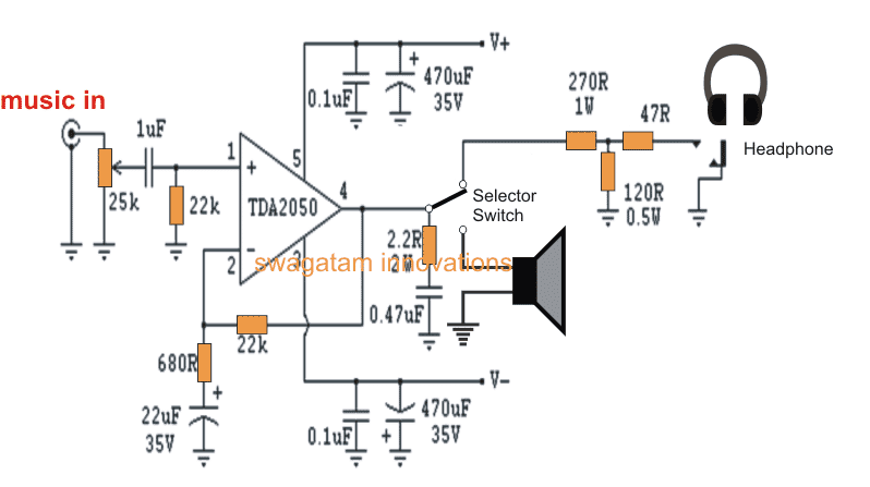
TDA2050 Single Amplifier Circuit

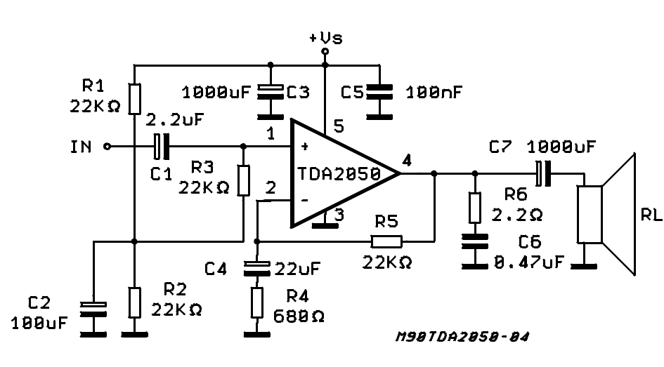
The first circuit features the TDA2050, a popular monolithic integrated circuit designed for use as a Hi-Fi audio power amplifier. This circuit is capable of delivering a respectable 32W of output power. The TDA2050 is known for its low distortion, high output current, and single supply operation, making it relatively simple to implement. The core of the circuit revolves around the TDA2050 IC. The input signal enters through a coupling capacitor, which blocks any DC voltage that might be present in the source signal, preventing it from affecting the amplifier's bias. Resistors and capacitors set the gain and frequency response of the amplifier. The feedback network, typically composed of resistors, plays a crucial role in stabilizing the amplifier and reducing distortion. The output stage delivers the amplified signal to the speaker, often through an output capacitor or a series inductor/resistor combination for stability. This ensures minimal output offset voltage. The TDA2050 also includes internal protection features, such as over-temperature and short-circuit protection, adding to its reliability.
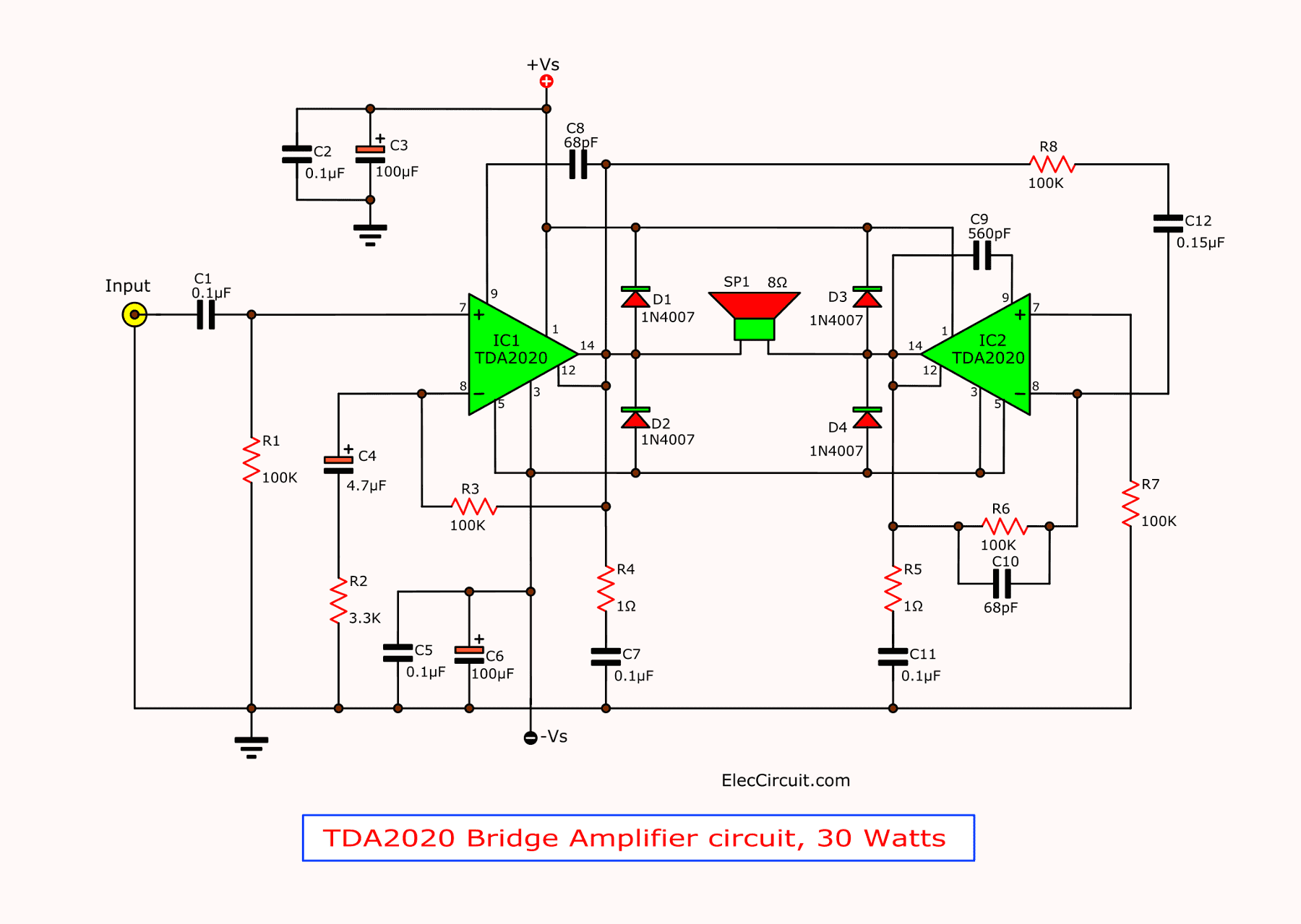
TDA2003 Bridge Amplifier 18W Circuit

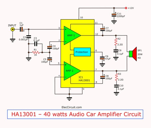
The second circuit utilizes the TDA2003 in a bridge configuration. This configuration allows for higher power output compared to a single-ended amplifier using the same IC. In this case, it can deliver up to 18W of power. A bridge amplifier effectively doubles the voltage swing across the load (speaker), leading to a quadrupling of the power output (since power is proportional to the square of the voltage). The TDA2003 is another popular audio amplifier IC, often found in car radios and other similar applications. It's known for its robustness and ease of use. In a bridge configuration using TDA2003, two TDA2003 amplifiers are used. The input signal is applied to one amplifier, while an inverted version of the same signal is applied to the other amplifier. The speaker is then connected between the outputs of the two amplifiers, creating a "bridge." The input stage typically involves coupling capacitors to block DC and resistors to set the input impedance. The TDA2003 amplifiers themselves are configured with feedback networks to control gain and stability. Decoupling capacitors are essential for providing a stable power supply voltage and preventing oscillations. Because the speaker is connected between the outputs of the two amplifiers, there is no need for an output coupling capacitor. The bridge configuration effectively eliminates any DC voltage across the speaker. The advantages of this bridge configuration include increased power output compared to a single-ended configuration, improved efficiency, and elimination of the need for a bulky output capacitor. However, it also requires careful matching of the gains and phase responses of the two amplifiers to ensure optimal performance.
Both of these circuits provide viable options for building audio amplifiers. The TDA2050 offers higher power and hi-fi quality, while the TDA2003 bridge configuration provides a good balance of power and simplicity. Choosing the right circuit depends on the specific requirements of your project and your skill level.
If you are searching about tda7294 bridge amplifier circuit diagram Electronics Projects - TRONICSpro you've visit to the right web. We have 25 Images about tda7294 bridge amplifier circuit diagram Electronics Projects - TRONICSpro like 30 Watts Audio Amplifier Circuit with TDA2050 IC, TDA2050 Subwoofer Amplifier Circuit Diagram using JRC4558 IC and also Lm1875 Audio Power Amplifier OTL OCL Low Distortion - Xtronic. Here it is:
Tda7294 Bridge Amplifier Circuit Diagram Electronics Projects - TRONICSpro
 tronicspro.com
 Tda2050 Bridge Amplifier Circuit Diagram
 ampli.deminasi.com
 Tda2050 Bridge Amplifier Circuit Diagram Pdf
 guidediagramlaxator.z14.web.core.windows.net
 La4440 Bridge Stereo Amplifier Circuit Diagram – Artofit
 www.artofit.org
 Tda2050 Bridge Circuit Tda2050 Amplifier Circuit Tda2050 Amplifier
 atelier-yuwa.ciao.jp
 Tda7294 Bridge Amplifier Circuit Diagram
 diagram2uma1p2awes.z21.web.core.windows.net
 30 Watts Audio Amplifier Circuit With TDA2050 IC
 www.pinterest.com
 Circuit 32w Hi-fi Audio Power Amplifier – TDA2050 | Xtronic
xtronic.org tda2050 amplifier circuit power audio 32w fi hi pcb single amp xtronic tweet
Tda2050 Bridge Amplifier Circuit Diagram - Circuit Diagram
 www.circuitdiagram.co
 TDA2050 Subwoofer Amplifier Circuit Diagram Using JRC4558 IC
 www.pinterest.com
 Tda2050 Bridge Amplifier Circuit
 diagrammanualbirgit.s3-website-us-east-1.amazonaws.com
 32 Watt Amplifier Circuit Using Tda2050 - Vrogue.co
 www.vrogue.co
 Tda2050 Bridge Amplifier Circuit
 diagrammanualbirgit.s3-website-us-east-1.amazonaws.com
 TDA2050 Amplifier With Current Environmental Protection - Amplifier
 amplifiercircuit.net
 tda2050 audio amplifier circuit protection environmental current gr next circuits 2011
Tda2030 Bridge Amplifier Circuit - Daily Pass
 daily-pass1.blogspot.com
 Tda2050 Bridge Amplifier Circuit Diagram Pdf
 userengineflokati.z14.web.core.windows.net
 TDA2003 Bridge Amplifier 18W Circuit - Tronicspro - TRONICSpro
tronicspro.com Lm1875 Audio Power Amplifier OTL OCL Low Distortion - Xtronic
 xtronic.org
 TDA2050 Amplifier Circuit Board 32W - Xtronic
 xtronic.org
 tda2050 amplifier circuit tda 2050 fi hi power audio amplificador schematic esquema 32w amp pcb xtronic suggested
Tda2050 Bridge Amplifier Circuit Diagram Pdf - Circuit Diagram
 www.circuitdiagram.co
 TDA2050 Audio Amplifier IC Pinout, Datasheet, Features, 52% OFF
 www.pinnaxis.com
 Stereo Amplifier TDA7297 Dual-Bridge Circuit | Stereo Amplifier, Audio
 www.pinterest.com
 TDA2030 Bridge Amplifier Circuit Diagram With PCB, 35W RMS, 41% OFF
 www.oceanproperty.co.th
 TDA2050 Amplifier Stereo 35W-75W
 www.eleccircuit.com
 tda2050 75w amplifier stereo power using project figure
TDA2030 Datasheet Audio Amplifier Circuits Pinout | ElecCircuit.com
 www.eleccircuit.com
 amplifier circuit tda2030 watt circuits eleccircuit tda2050 pcb datasheet amplifiers stereo pinout watts 2030 subwoofer 35w 12v transistor rms 75w
Tda2030 bridge amplifier circuit diagram with pcb, 35w rms, 41% off. Tda2050 amplifier circuit tda 2050 fi hi power audio amplificador schematic esquema 32w amp pcb xtronic suggested. La4440 bridge stereo amplifier circuit diagram – artofit


