When it comes to electrical projects, understanding the intricacies of relay circuits can be a game-changer for both hobbyists and professionals alike. In this ultimate guide, we delve into the world of 12V relay circuit diagrams, breaking down their components, functionality, and practical applications. Whether you're looking to automate a simple task or integrate complex systems, mastering the 12V relay will enhance your project's efficiency and reliability. Join us as we explore detailed diagrams, essential tips, and troubleshooting advice to empower your electrical endeavors.
Relay Wiring Diagram Relay Connection Relay Working, 53% Off
In any electrical project, understanding the relay wiring diagram is crucial for ensuring proper connections and functionality. A relay acts as an electromechanical switch that allows you to control a high-power circuit with a low-power signal, making it an essential component in various applications. The relay connection typically involves a coil and a set of contacts; when a voltage is applied to the coil, it creates a magnetic field that closes (or opens) the contacts, enabling or disabling the flow of current in the circuit. For those looking to enhance their DIY skills, our comprehensive guide on the 12V relay circuit diagram not only simplifies the wiring process but also offers a fantastic 53% off on select components, making it easier than ever to dive into your electrical projects with confidence.
 gisli.mx
 12v Relay Module
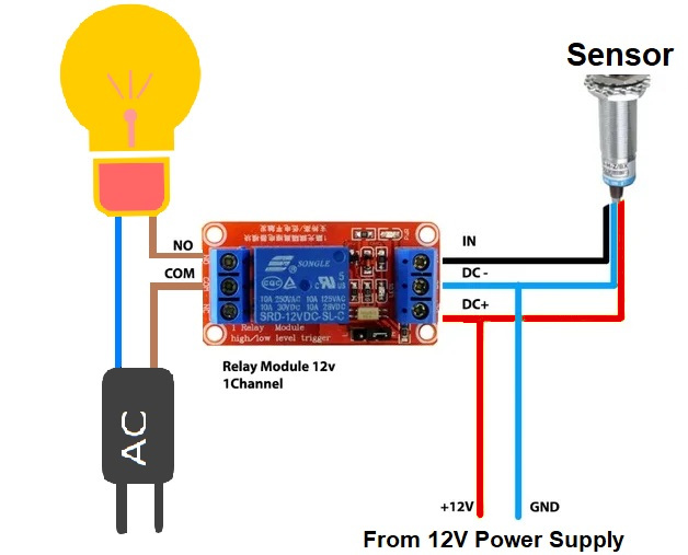
A 12V relay module is an essential component in many electrical projects, acting as a switch that allows you to control high-voltage devices using low-voltage signals. This module typically consists of one or more relays, each capable of handling significant current loads, making it ideal for applications such as home automation, automotive systems, and industrial controls. The beauty of a 12V relay module lies in its ability to isolate the control circuit from the load circuit, ensuring safety and preventing damage to sensitive components. In our ultimate guide on the 12V relay circuit diagram, we will delve into the wiring configurations, operational principles, and practical applications of these modules, empowering you to enhance your electrical projects with reliable and efficient control solutions.
 mungfali.com
 12v Relay Diagram 4 Pin
In the realm of electrical projects, understanding the 12V relay diagram, particularly the 4-pin configuration, is crucial for both hobbyists and professionals alike. A 4-pin relay typically consists of two pins for the coil and two for the switch contacts. When a 12V voltage is applied to the coil pins, it generates a magnetic field that activates the switch, allowing current to flow through the contact pins. This simple yet effective mechanism enables you to control high-power devices using low-power signals, making it an essential component in various applications, from automotive systems to home automation. By mastering the 12V relay diagram, you can enhance your projects with reliable switching capabilities while ensuring safety and efficiency in your electrical designs.
 www.prosecution2012.com
 Short Circuit Protection Using Relay For Batteries
In any electrical project involving batteries, implementing short circuit protection is crucial to ensure safety and longevity of the components. One effective method is utilizing a relay in your 12V circuit. A relay acts as an automatic switch that can disconnect the battery from the load in the event of a short circuit. When an overload occurs, the current surge triggers the relay to open, thereby preventing potential damage to the battery and connected devices. This simple yet essential addition to your circuit not only safeguards your equipment but also enhances the reliability of your electrical projects. In this guide, we will delve into the specifics of a 12V relay circuit diagram, illustrating how to integrate short circuit protection seamlessly into your designs.
 www.hackatronic.com
 5v Relay Circuit Diagram
In the realm of electrical projects, understanding the 5V relay circuit diagram is essential, especially when working with a 12V relay system. A 5V relay acts as an intermediary switch that allows low voltage signals to control higher voltage devices safely. Typically, the circuit consists of a 5V power supply, a relay module, and a controlling device, such as a microcontroller or a switch. The diagram illustrates the connections between these components, highlighting the relay's coil, which is energized by the 5V signal, and the switch contacts that control the higher voltage circuit. By mastering the 5V relay circuit, you can effectively integrate it into your 12V relay projects, ensuring reliable operation and enhanced functionality in your electrical endeavors.
 www.circuitdiagram.co
 Other Wiring Gallery

electrical.creative-ae.com
Earth Leakage Relay

circuitrustyrosesims3v3.z21.web.core.windows.net
Magnetic Relay Circuit Diagram
www.circuitdiagram.co
5v Relay Circuit Diagram

rainowfag0yzguidefix.z14.web.core.windows.net
Relay Diagram Explained
gisli.mx
Relay Wiring Diagram Relay Connection Relay Working, 53% Off

www.circuitdiagram.co
12 Volt Relay Circuit Diagram

wiredraw.co
12 Volt Relay Circuit Diagram

www.circuitdiagram.co
You Might Also Like: Electric Trailer Brakes Wiring Master
5v Relay Circuit Diagram


